Christus Spohn Hospital
Location
Size
Design Architect
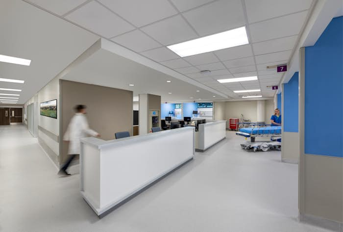
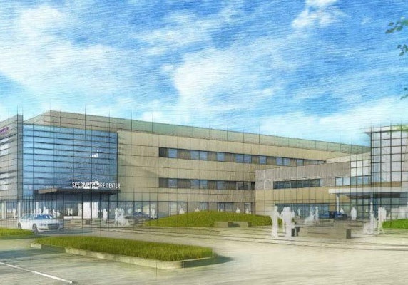
Corpus Christi’s Christus Spohn Hospital is adding its new 10-story Shoreline Tower that will provide 216 new patient beds, an expanded emergency department with 55 new beds, a level II trauma center, interventional radiology and endoscopy, a graduate medical education residency programs, a new main entrance, and a large new lobby. The tower is constructed on the site of a former parking garage.
Process
This project’s coastal location results in a high design wind speed. The basic wind speed per ASCE 7-10 is 152 MPH (120 MPH nominal wind speed). In addition to the building code requirements, this project must comply with the Texas Department of Insurance’s (TDI) Windstorm Inspection Program.
The new Tower’s immediate proximity to two existing buildings required the Tower’s foundation system to be offset in the plan to avoid undermining the in-place auger cast pile foundations. Working with the Owner’s geotechnical engineer, Terracon, and McCarthy Construction, a foundation system consisting of auger cast piles below pile caps and drilled piers was selected. The vast majority of the new foundation is auger cast piles with the drilled pier locations limited to high axial loads at the sheer walls, high axial loads at the elevator core walls, and the columns immediately adjacent to the existing buildings.
Level one floor framing options were studied to address the balance between initial construction cost, life-cycle costs, and future flexibility. After review and discussion with the Owner, a slab-on-grade system was selected. Similarly, elevated structural framing systems were documented and reviewed by the project team. A cast-in-place concrete two-way flat slab was selected for the elevated framing. This selection was largely driven by the need to maximize ceiling plenum space within the short floor to floor heights, which were required to match the adjacent existing buildings. Floor penetrations at each level were closely coordinated with the architectural and MEP teams since floor penetrations near columns in a two-way system can be structurally problematic.


The new lobby space is a tall volume extending from level 1 to level 3. In plan, the level 1 perimeter extends beyond the tower perimeter at levels 3 and 4. The architectural concept had small columns along the exterior lobby walls to maximize views through the exterior curtain wall. Fortunately, the offset between podium and tower plans yielded much smaller column axial loads, which helped minimize the lobby column sizes. To further minimize the column plan dimensions, structural steel tubes were utilized. A rectangular tube shape was selected since the curtain wall system is braced by level 2 horizontal tube framing that imposes column bending as the perimeter columns span from level 1 to level 3. To eliminate interior columns within the new lobby, post-tensioned beams were designed and detailed at level 3 to accommodate the longer spans.
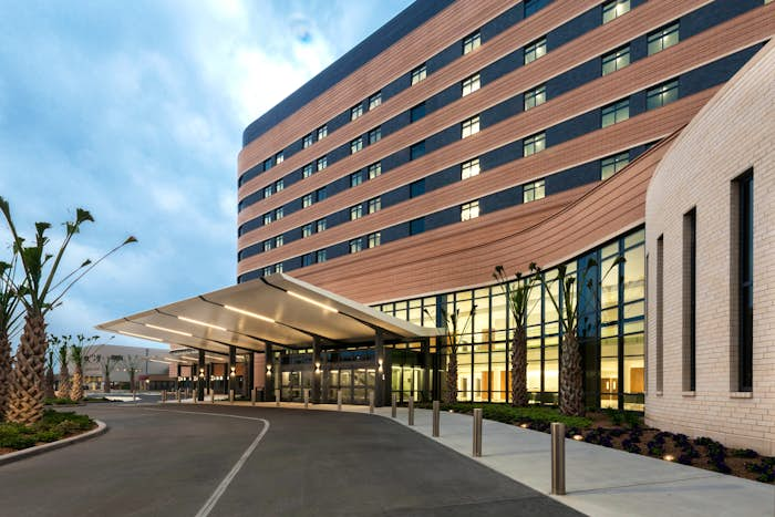
The new Tower’s main entrance and emergency department canopies are structurally unique. Several canopy schemes were investigated but were ultimately proven to be too expensive. The selected canopy scheme has architecturally exposed steel tubes supporting an architecturally exposed, post-tensioned, tapered, concrete slab. The draped slab post-tensioning minimizes concrete thickness and increases stiffness. The concrete’s weight is beneficial in the wind load cases as the concrete weight offsets the wind uplift pressure.