
Parkland Hospital
Location
Size
Design Architect
Largest Public Healthcare Project in the US to be Built in One Phase
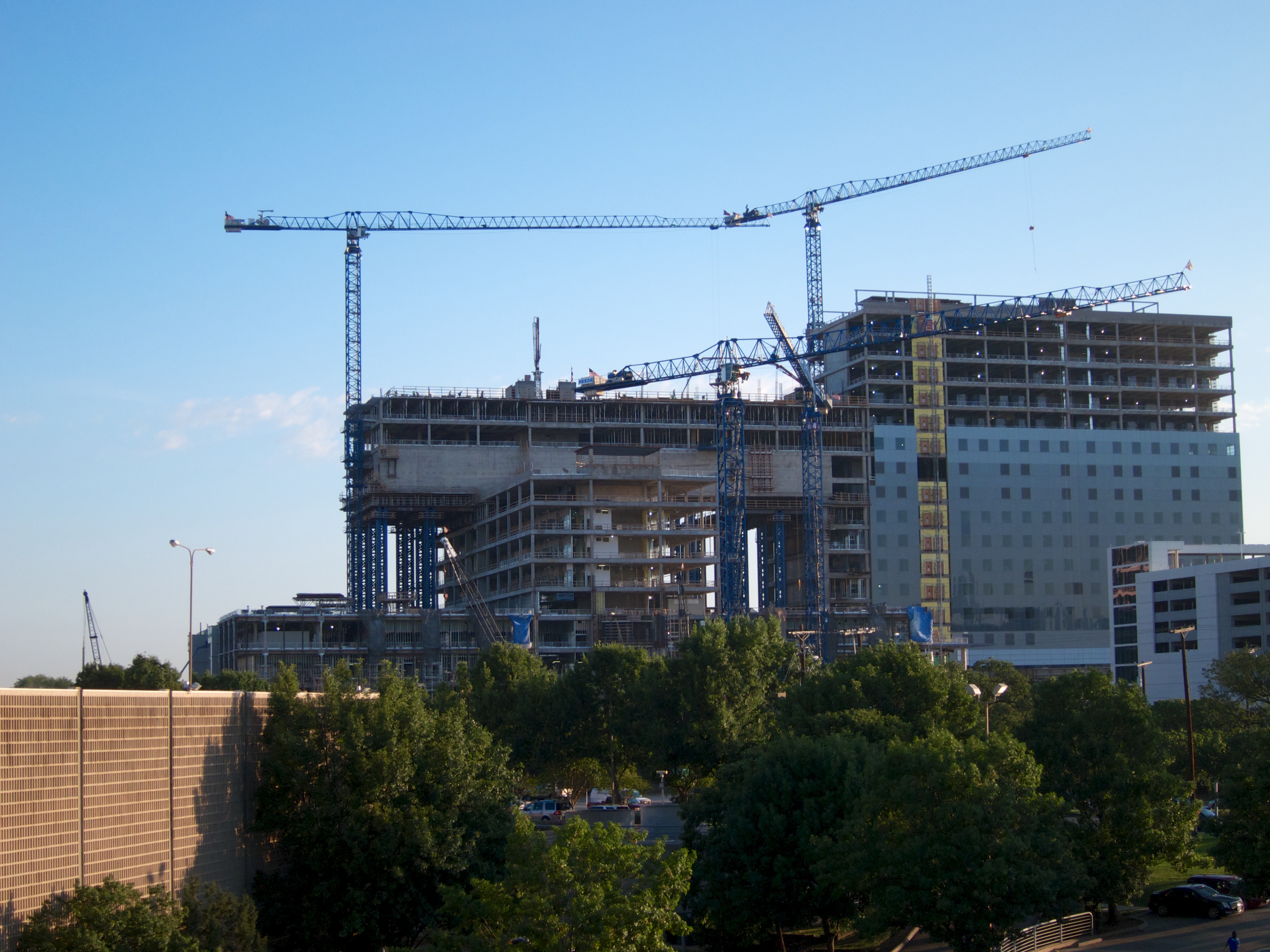
Dallas’ Parkland Hospital, built in the 1950s, was functionally inadequate for 21st century needs and many complaints and state-issued mandates pushed the owner to reach out to consultants to develop a new architectural and engineering vision. A large structure evolved, resulting in unusual engineering challenges.
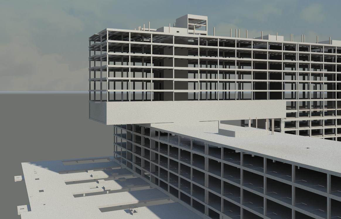
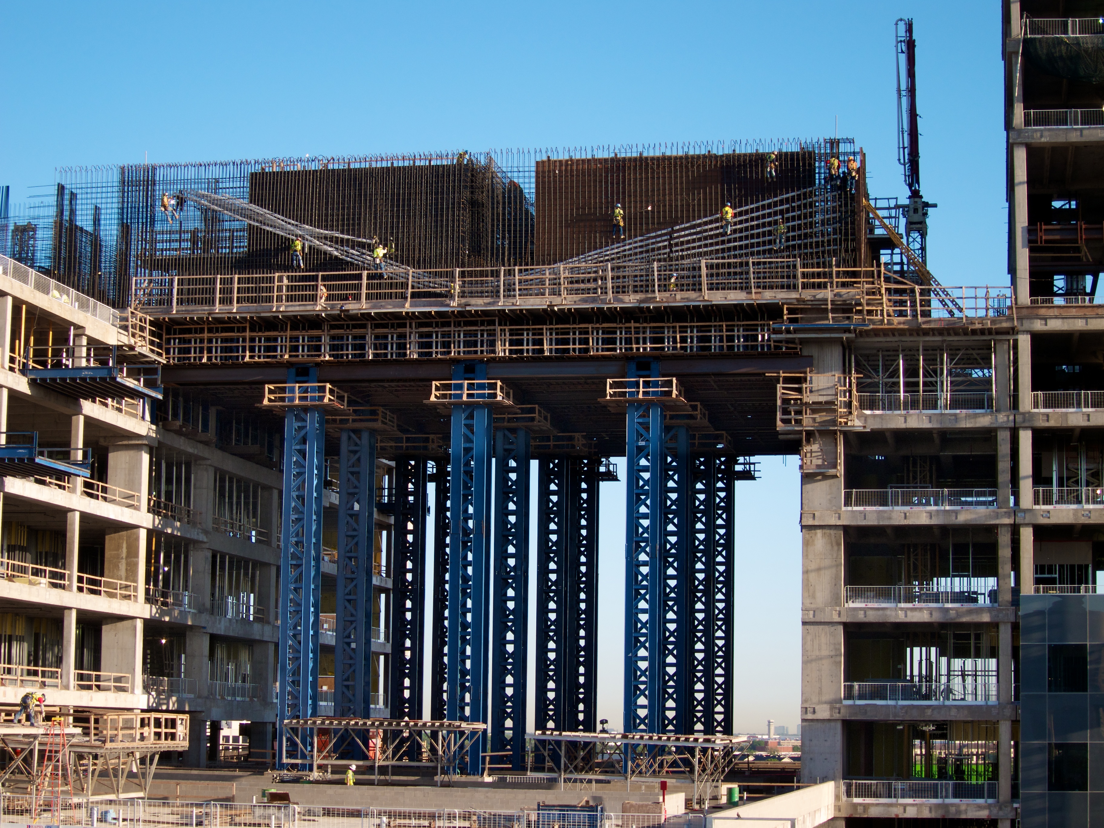
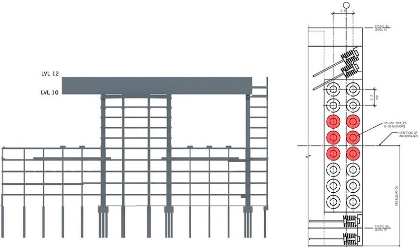
The owner mandated that design concept allows for the highest number of windows, an important criterion in terms of patient comfort and sense of well-being. The architectural team and the owner recognized the magnitude of the concept and its cost became a prominent issue. For the concept to advance, the structural team was challenged to select the most economical method of creating the desired form. This was accomplished with a system of 30-ft-deep, post-tensioned transfer walls/girders. These elements were designed to be stressed in 8 stages. The form consists of a 62-ft cantilever, coupled with a 120-ft span over an opening; both support seven stories above. As structural engineers, we had our work cut out for us; but the team was up to the task, developing a 5-step process to bring the concept to fruition, at a cost that could meet the owner’s needs.
Process
As structural engineers, we had our work cut out for us; but the team was up to the task, developing a 5-step process to bring the owner's concept to fruition, at a cost that could meet their needs.
1.A: The Alternative Systems Study
The initial step for the structural engineers was to identify potential structural systems, which they could then submit to a general contractor for pricing. The first option involved a two-story structural steel transfer girder between the 10th and 12th floors; but the structural engineers’ calculations determined the deflections were unacceptably high and that the steel tonnage was clearly unrealistic based on the size and structure of the building. The second option included adding steel diagonals from the 10th floor to the roof to create a seven-story truss. This proved to be a more cost-effective solution.
1.B: The Vibration Factor
With any steel system, the structural engineers have an inherent concern about vibration. This is overcome by adding structural steel tonnage or a thicker composite concrete slab to increase mass. Either option dampens vibration. Nevertheless, this leads to additional costs. Also, locating the diagonals through the floors could create significant functional coordination issues between the architects and mechanical engineers. The contractor also expressed major concerns about the cost of this concept, but the structural engineers chose to provide sufficient drawing details to allow the contractor to proceed in developing a proper cost estimate.
2.A: Primary Role of the Structural Engineer
The primary role of the structural engineer is to prepare construction documents for the structure, including plans and specifications.To prepare such documents for the hospital, the structural engineers performed all of the structural calculations to establish the strength and size of the concrete members, the size and spacing of the reinforcing steel, and the foundations to support the building. These calculations must be extremely precise and include calculations of stress due to dead load, wind loads and live load, creep of the concrete, and deflection of the structural elements.
2.B: Design Criteria for Constructability
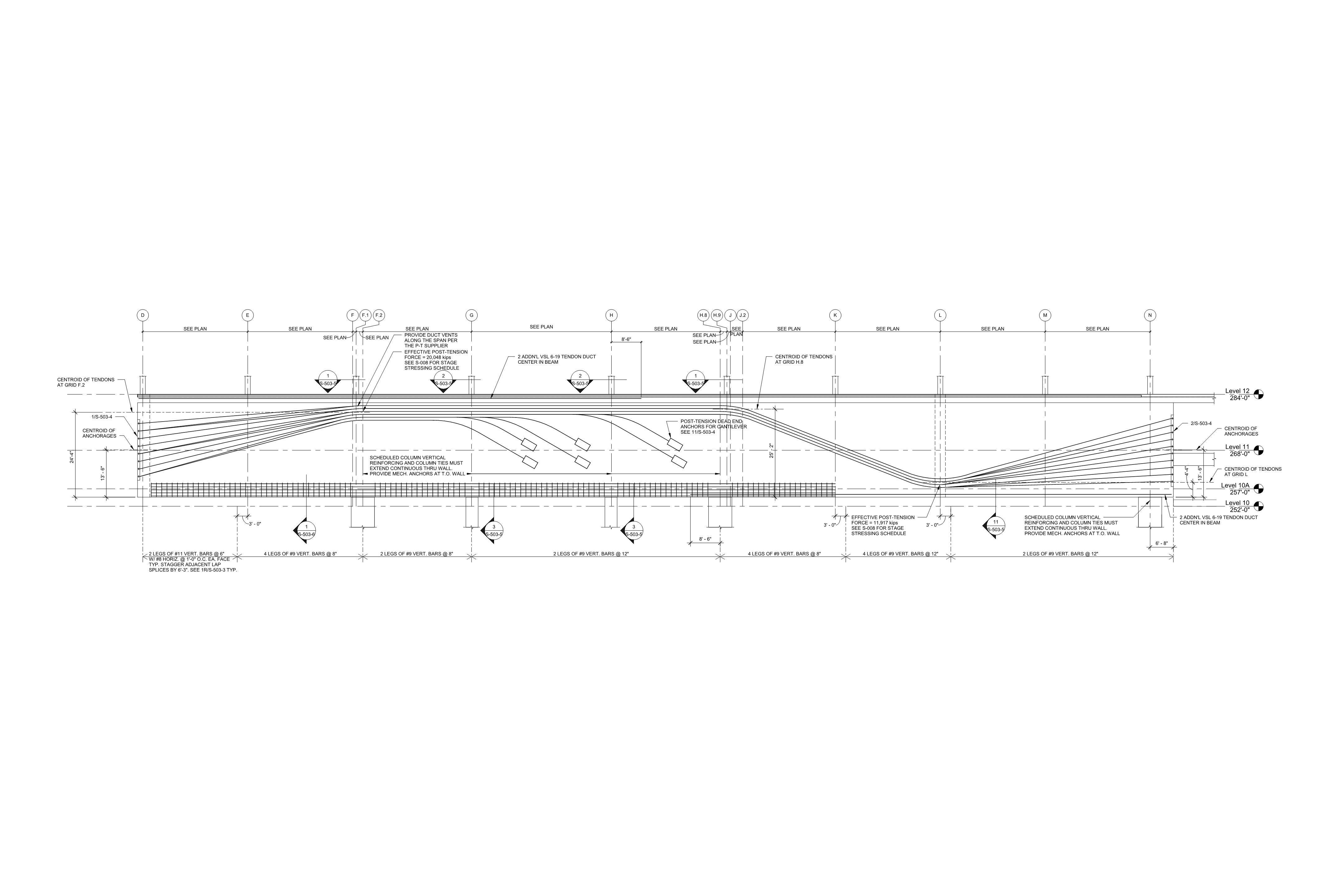
The next step was to investigate the final details of the transfer girder and the stage stressing associated with the post-tensioned solution. Since the transfer girder is considered to be a deep beam by the American Concrete Institute, Craig Rios of Datum Engineers prepared in-depth "strut and tie" calculations. These had to be developed before the design could be completed. For a girder of this size and importance, the structural engineers specified bonded post-tensioning cables. In this approach, the post-tensioning tendons are installed inside of the conduits and then grouted after the tendons are stressed.
3.A: Concrete Shoring Concept
Design of steel shoring to support the wet weight of concrete is a major engineering consideration. Datum Engineers created the forming concept for the concrete contractor to assure all construction issues were properly addressed from a structural point of view. Structural design of the building and practical constructability were very closely coordinated with the five-story-tall shoring system supported on the 5th floor. The 5th floor had to be designed to support the concrete weight of the transfer girder and the 10th and 12th floors. Since the design of the roof at the 5th floor had to support the load, the engineers needed a clear understanding of how the contractor was going to shore all this dead weight at the 5th floor. This would allow engineers to design the beams and the columns at the 5th floor to safely and adequately support that load. The structural team coordinated with the contractor to locate the beams and columns of the shoring system and determined the locations that would be the most cost-effective to strengthen the roof at the 5th floor. Pre-planning this process provided a major contribution to the success of the project.
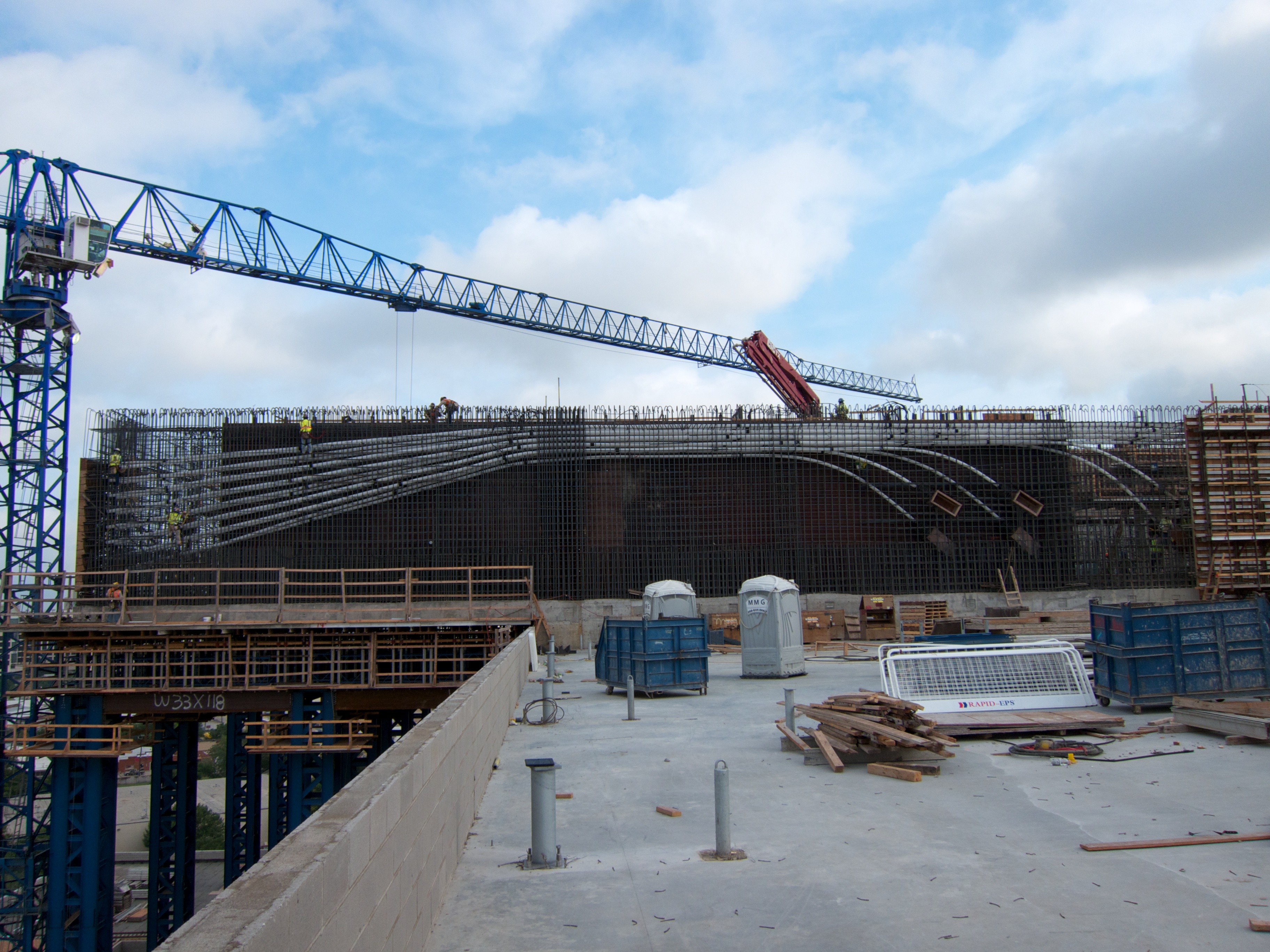
3.B: Stage Stressing the Post-Tensioning Tendons
The post-tensioning solution included stage stressing and grouting of the tendons. The tendons were installed and stressed as each floor was poured. The amount of stress was applied to support the weight of the addition of each floor and, after stressing, the tendons were grouted. Each floor was cast level and then the contractor would cast the next floor. When construction of each area began, the weight of the transfer girder on the 10th floor required the post-tensioning of six conduits. There are 31 tendons in each conduit. After pouring the transfer girder, and tensioning the six conduits, the next floor was poured. This step-and-repeat process was continued until the roof was poured and completed. A stressing jack was used to stress the tendons in the conduit at the end of the transfer girder.
4.A: Quality Control Process
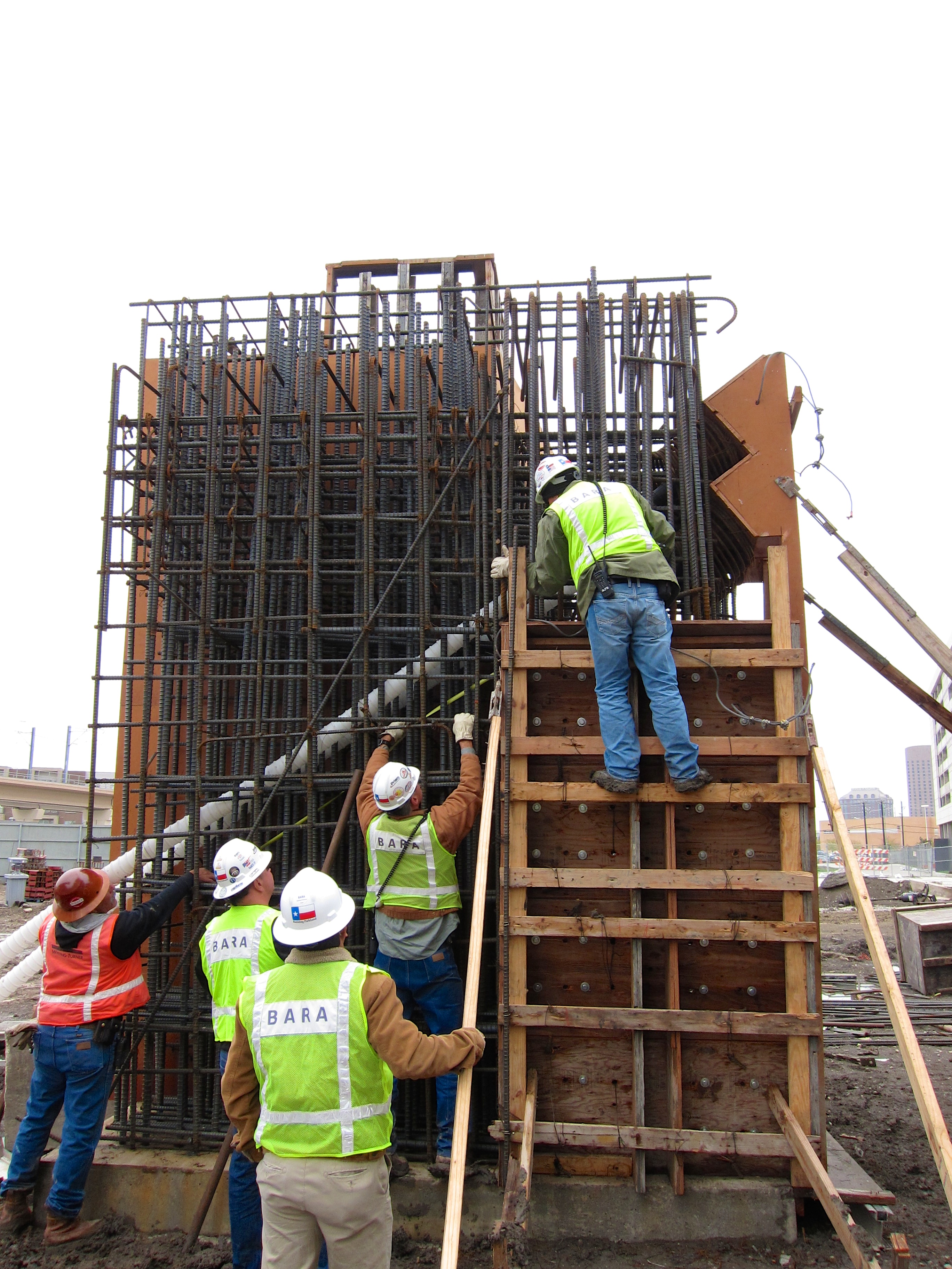
Quality control was another extremely important part of the success of this complex project. In addition to a highly successful structural engineering design, contractor team coordination, testing laboratory inspections, concrete testing, and all of the pre-planning that goes into a project, the contractor also proposed building a mock-up of the highly congested corner condition.
As the largest public healthcare project in the country to be built in one phase, Parkland “serves as a standard for public healthcare development into the future."
Lou Saksen Senior Vice President for New Parkland Construction, as quoted in Building Design & Construction magazineKey Team Members


Awards
Concrete Reinforcing Steel Institute
CRSI HONORS Design & Construction Awards
Post-Tensioning Institute
Award of Excellence / Buildings
ACEC Texas Engineering Excellence Awards
Silver Medal Winner
Regional Hispanic Contractors Association
Project of the Year - 8th Annual Pillars Awards
Building Design & Construction Magazine
Building Team Gold Award